Chapter 2 Basic Circuit Connections and Laws
2.1 Circuit Terminology
Node: junction of two or more circuit elements.
Essential node: junction of three or more circuit elements.
Path: set of one or more adjoining circuit elements that may be traversed in
succession without passing through the same node more than once. A path
generally has an initial node at its beginning and a final node at its end.
If the initial and final nodes are the same, the path is closed and becomes a loop.
Mesh: a loop that does not enclose any other loop.
Branch: path that connects two nodes.
Essential branch: branch that connects two essential nodes without passing
through an essential node.
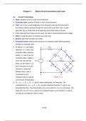
In Figure 2.1.1 the nodes 1 Rsrc a
labeled a, b, c, and d, are L1
essential nodes, whereas
nodes 1, 2, and 4 are not C2 R1
2
essential nodes. Nodes 3 R5
vSRC +
and b are one and the c b
– 3
same, as are nodes 3’, d,
4 C3
and 5 because no circuit R4
element is connected 3'
L4
between them, only a R3
connection of zero 5 d
resistance that is used for Figure 2.1.1
convenience of illustration.
Rsrc, vSRC, L1, R1, L4, R4, C3, and R3 taken individually, are branches. The
combinations Rsrc-vSRC, L1-R1, L4-R4, and the individual branches C3 and R3 are
essential branches. The closed paths d-5-1-a-b-d and d-5-1-a-c-b-d are loops. The
loops d-5-1-a-c-d, a-b-c-a, and d-c-b-d (going through C3) are meshes. C3 and R3
can also be considered to form a mesh.
2-1/16
,2.2 Kirchhoff’s Laws
Kirchhoff’s Current Law
Statement At any instant of time, the sum of currents entering a node is equal
to the sum of currents leaving the node.
At node N in Figure 2.2.1 KCL gives: iA + iB = iC + iD.
KCL is a direct expression of conservation of current, which iC
follows from conservation of charge, just as conservation of power iA iB
follows from conservation of energy.
N
Alternative statement of KCL: at any instant of time, the algebraic iD
sum of all the currents at any node is zero.
Figure 2.2.1
iA + iB −i C −i D =0 , where opposite signs are assigned to currents
flowing towards the node and to currents flowing away from the node.
KCL may be applied S S
not just to a node i
i=0
but also to
A B A B
interconnected
circuits or parts of a i
(a) (b)
circuit.
Figure 2.2.2
Figure 2.2.2a:
equal and opposite currents flow in the two connections. In Figure 2.2.2b, i = 0.
Kirchhoff’s Voltage Law
Statement At any instant of time, the sum of voltage rises around any loop is
equal to the sum of voltage drops – v3 +
around the loop. + +
v2 3 4
v1 + v2 + v3 = v4 + v5 in Figure 2.2.3. v4
–
Equivalent statement of KVL: at any instant of –
2 +q 5
time, the algebraic sum of the voltages around
any loop is zero, since voltage drops and + +
v1 1 v5
voltage rises have opposite signs: – –
v1 + v2 + v3 – v4 – v5 = 0.
Concept KCL and KVL together are an Figure 2.2.3
2-2/16
, expression of conservation of energy.
In taking a charge +q clockwise around the loop, the work done on the charge is q(v1
+ v2 + v3). But the charge can do more work, q(v4 + v5), if (v1 + v2 + v3) < (v4 + v5),
which violates conservation of energy. Taking the charge +q around a loop, which
necessarily involves passing through nodes or essentials nodes between the circuit
elements, implies that the charge +q is conserved at these nodes, that is, KCL
applies.
2.3 Voltage Division and Series Connection of Resistors
Definition In a series connection of elements, the same current flows
through all the elements.
In Figure 2.3.1a: + v1 – + v2 – i + vn –
a
v SRC =v 1 + v 2 +. ..+ v n
R1 R2 Rn
(2.3.1) vSRC +
Applying Ohm’s law to –
i
the individual resistors:
b (a) i
v SRC =R 1 i+ R 2 i+. . .+ R n i a
(2.3.2)
vSRC + Reqs
If Rm denotes one of the
–
resistors R1 to Rn and vm b i
is the voltage drop
Figure 2.3.1 (b)
across Rm, so that vm =
Rmi, then dividing this relation by Equation 2.3.2:
vm Rm
=
v SRC R 1 + R2 +. . .+ R n , m = 1, 2, …., n (2.3.3)
vSRC divides across the string of resistors in the ratio of each individual resistance to
the total resistance. If vSRC = 6 V, R1 = 1 , R2 = 2 , and R3 = 3 , the voltages
across the resistors are v1 = 1 V, v2 = 2 V, and v3 = 3 V.
It also follows that the voltages across any two resistors are in the ratio of the
corresponding resistances and in the inverse ratio of the conductances:
v1 R1 Gm
= =
vm Rm G1 (2.3.4)
2-3/16


