1 Name Surname - XXXXXXX
ES196 Engineering Structures Lab Report: Pin-Jointed
Trusses
Name Surname - XXXXXXX
March 20, 2025
Abstract
In this lab, we tested a roof truss structure against 3 different load cases to gain a greater understanding
of their behaviors. We used a TecQuipment Pin-Jointed Framework [1] to test how various loads of different
types and magnitude impact the internal strains and forces of the truss, using a digital force meter of
uncertainty 0.5% and strain display of uncertainty 0.83%. Loads of various magnitudes were applied, with
the true strain measured and used to calculate the internal force of each member of the truss. The existence
of non-force members is analysed, with one being activated in load cases 2 and 3 due to the existence of
the horizontal component in the angled load. The final load case, which combines the two loads for a more
realistic scenario, demonstrates the principle of superposition with thed combined force being equivalent to
the sum of the two individual forces.
1 Introduction
1.1 Aim
The primary aim of this lab is to understand the concepts behind pin-jointed trusses through the application of
a variety of load cases to its members. The strains of each are experimentally measured and linked to the forces
carried by the members of the truss. This can be useful in analysing and gaining an increased understanding of
how forces internally interact within a truss. The knowledge of this is vital, with trusses being a commonplace
engineering structure, with applications in bridges and rollercoasters. The most famous example of this would
be the Eiffel Tower, containing over 15,000 girders at 30,000 points [2].
1.2 Background Theory and Information
Trusses consist of straight members connected at joints so that they only carry axial forces such as tension
or compression. They are very efficient i.e all the material is being used close to its failure stress. This is
especially compared to beams, which act in bending and therefore have a high amount of non-highly stressed
material. Therefore, trusses are useful in light, strong and stiff structures such as bridges.
Three conditions are required to ensure truss members only behave in tension and compression and does not
collapse [3]:
• All loads on a truss must be applied at the nodes where members meet (or bending occurs)
• All connections between members must allow members to rotate relative to each other (or bending occurs)
• Trusses must consist of a number of triangles (or collapses)
The experiment requires you to experimentally measure the strain in various load cases. This is used to
calculate experimental forces given a certain load. To calculate this, we can use the Young Modulus formula:
σ F F
E= AN D σ = −→ E = (1)
ϵ A Aϵ
We can further use the formula for cross-sectional area to expand this formula
πD2 4F
A= −→ E = (2)
4 πD2 ϵ
EπD2 ϵ
∴F = (3)
4
When analysing trusses to determine the theoretical forces, the primary method used would be the Method
of Joints:
With this, you would treat the truss as a rigid body to find the external reactions through making a free-
body diagram and applying the 3 equations of equilibrium. This is based on the fact that if entire truss is in
equilibrium, so are each of its joints. Therefore with free-body diagram can use ΣFx = 0 and ΣFy = 0 to
obtain member forces on each joint
When using this method, first start at a joint with only two members and treat it as a free body. Therefore
applying the equations above can help solve for the two unknown forces. Later can move onto adjacent joints
where forces are unknown and solve for them [4].
, 2 Name Surname - XXXXXXX
2 Methods and Apparatus
2.1 Apparatus
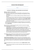
This lab uses the TecQuipment ”Pin-Jointed Framework” (STR8) as
used in figure 1. This is precision engineered for this experiment and
consists of stainless steel member which are used alongside bosses as
well as pin and roller supports to produce a ”roof” shape framework
as shown in figure 2. To support the framework, a benchtop structures
platform (STS1) is used to provide a stable base to conduct the ex-
periment on. This can be seen as number 4 in figure 1. The compact
size and low centre of gravity provide a substantial benefit as they al-
low the equipment to be used ”easily and at an ergonomic height” [5]. Figure 1: Image showing experimental
The STR8 Framework initially comes with a singular load cell cell to setup for Truss Lab. 1 = Load Cell,
apply a load onto the truss structure at various angles and magnitudes 2 = Digital Force Display, 3 = Digi-
as shown by number 1 in figure 1. However, the actual setup used in tal Strain Display, 4 = Structures Test
the experiment utilises a roof structure with an additional angled load Frame
cell (utilised in Load Cases 2 and 3) such as in figure 2. Therefore,
an extra load cell is needed from TecQuipment(STR8A). As indicated
by number 2 on fig. 1, an optional Digital Force Cell (STR1A) is
connected to the load cell(s) to measure the applied load. This has a
resolution of 1N for under 500N (as would likely be neccesary here)
where the range is auto-selected. The strain of each member can also
be found through a strain-gauge which is connected to a digital strain
display that has a resolution of 1µϵ. Finally, an improvement that
could be made in terms of apparatus would be to make use of the
STR2000 Automatic Data Acquisition Unit and its software to more
simply and efficiently plot and analyse data [6].
2.2 Methods
Figure 2: Diagram for Truss Lab Setup
In this experiment, we look at the impact of various forces a typical
roof truss would have to withstand. For this, there are 3 methods for
the different load cases looking at different types of forces. However,
there are some initial steps needed to setup and calibrate the experiment:
1. Inspect the equipment and ensure there is no damage to the wiring or any connections.
Turn on the power supply for the force and strain displays. For 5 minutes, allow the equipment to warm up
2.
and stabilise.
Ensure no force is being applied via the load cells by spinning the central knobs (if so, release it by turning
3. the handle). Now check the digital display shows zero for both cells and, if not, zero the output using the
adjustment knobs.
Check the digital strain display for channels 1-13 for the different truss members and ensure they give a reading
4.
of 0. If not, adjust them using a small screwdriver to turn the screw next to the gauge input socket.
The first load case is of a single central force acting downwards. The aim of this is to represent the load
from a water tank, for instance. Firstly, ensure the pin is only in load cell W1 for the downwards load. Next,
record the values for channels 1-13. Apply a force of 100N by turning the handle anti-clockwise on the load
cell. Ensuring the digital force display is reading channel 1 (for load cell W1 ), record the ”raw” value from the
digital strain display for channels 1-13. Subtract the inital values for each channel/member to find the ”true”
strain (and eliminate zero error) which you record like in table 2. Repeat for loads of 200/300/400/500N. Later
calculate the theoretical and experimental forces for these values to put in table 3
The second load case is an angled force and its aim is to represent the impact of wind, for example, on a roof
truss. Ensure that the pin is only in load cell W2 and the digital force display is reading channel 2. Otherwise,
you would follow the same steps to calculate the true strain as a result of force W2 in table 5.
Load case 3 has a combination of the central and angled force, being closer to emulating more natural or
realistic conditions. Firstly, ensure the pins are in both load cells (W1 and W2 ) and that they are free to rotate.
Then, you would apply a force of 500N for W1 and increase only W2 from 100N to 500N. Ensure that when
recording the values, the correct channel is selected to record the force for both load cells.
At the end of the experiment, ensure to switch off the power supplies to the digital meters.
ES196 Engineering Structures Lab Report: Pin-Jointed
Trusses
Name Surname - XXXXXXX
March 20, 2025
Abstract
In this lab, we tested a roof truss structure against 3 different load cases to gain a greater understanding
of their behaviors. We used a TecQuipment Pin-Jointed Framework [1] to test how various loads of different
types and magnitude impact the internal strains and forces of the truss, using a digital force meter of
uncertainty 0.5% and strain display of uncertainty 0.83%. Loads of various magnitudes were applied, with
the true strain measured and used to calculate the internal force of each member of the truss. The existence
of non-force members is analysed, with one being activated in load cases 2 and 3 due to the existence of
the horizontal component in the angled load. The final load case, which combines the two loads for a more
realistic scenario, demonstrates the principle of superposition with thed combined force being equivalent to
the sum of the two individual forces.
1 Introduction
1.1 Aim
The primary aim of this lab is to understand the concepts behind pin-jointed trusses through the application of
a variety of load cases to its members. The strains of each are experimentally measured and linked to the forces
carried by the members of the truss. This can be useful in analysing and gaining an increased understanding of
how forces internally interact within a truss. The knowledge of this is vital, with trusses being a commonplace
engineering structure, with applications in bridges and rollercoasters. The most famous example of this would
be the Eiffel Tower, containing over 15,000 girders at 30,000 points [2].
1.2 Background Theory and Information
Trusses consist of straight members connected at joints so that they only carry axial forces such as tension
or compression. They are very efficient i.e all the material is being used close to its failure stress. This is
especially compared to beams, which act in bending and therefore have a high amount of non-highly stressed
material. Therefore, trusses are useful in light, strong and stiff structures such as bridges.
Three conditions are required to ensure truss members only behave in tension and compression and does not
collapse [3]:
• All loads on a truss must be applied at the nodes where members meet (or bending occurs)
• All connections between members must allow members to rotate relative to each other (or bending occurs)
• Trusses must consist of a number of triangles (or collapses)
The experiment requires you to experimentally measure the strain in various load cases. This is used to
calculate experimental forces given a certain load. To calculate this, we can use the Young Modulus formula:
σ F F
E= AN D σ = −→ E = (1)
ϵ A Aϵ
We can further use the formula for cross-sectional area to expand this formula
πD2 4F
A= −→ E = (2)
4 πD2 ϵ
EπD2 ϵ
∴F = (3)
4
When analysing trusses to determine the theoretical forces, the primary method used would be the Method
of Joints:
With this, you would treat the truss as a rigid body to find the external reactions through making a free-
body diagram and applying the 3 equations of equilibrium. This is based on the fact that if entire truss is in
equilibrium, so are each of its joints. Therefore with free-body diagram can use ΣFx = 0 and ΣFy = 0 to
obtain member forces on each joint
When using this method, first start at a joint with only two members and treat it as a free body. Therefore
applying the equations above can help solve for the two unknown forces. Later can move onto adjacent joints
where forces are unknown and solve for them [4].
, 2 Name Surname - XXXXXXX
2 Methods and Apparatus
2.1 Apparatus
This lab uses the TecQuipment ”Pin-Jointed Framework” (STR8) as
used in figure 1. This is precision engineered for this experiment and
consists of stainless steel member which are used alongside bosses as
well as pin and roller supports to produce a ”roof” shape framework
as shown in figure 2. To support the framework, a benchtop structures
platform (STS1) is used to provide a stable base to conduct the ex-
periment on. This can be seen as number 4 in figure 1. The compact
size and low centre of gravity provide a substantial benefit as they al-
low the equipment to be used ”easily and at an ergonomic height” [5]. Figure 1: Image showing experimental
The STR8 Framework initially comes with a singular load cell cell to setup for Truss Lab. 1 = Load Cell,
apply a load onto the truss structure at various angles and magnitudes 2 = Digital Force Display, 3 = Digi-
as shown by number 1 in figure 1. However, the actual setup used in tal Strain Display, 4 = Structures Test
the experiment utilises a roof structure with an additional angled load Frame
cell (utilised in Load Cases 2 and 3) such as in figure 2. Therefore,
an extra load cell is needed from TecQuipment(STR8A). As indicated
by number 2 on fig. 1, an optional Digital Force Cell (STR1A) is
connected to the load cell(s) to measure the applied load. This has a
resolution of 1N for under 500N (as would likely be neccesary here)
where the range is auto-selected. The strain of each member can also
be found through a strain-gauge which is connected to a digital strain
display that has a resolution of 1µϵ. Finally, an improvement that
could be made in terms of apparatus would be to make use of the
STR2000 Automatic Data Acquisition Unit and its software to more
simply and efficiently plot and analyse data [6].
2.2 Methods
Figure 2: Diagram for Truss Lab Setup
In this experiment, we look at the impact of various forces a typical
roof truss would have to withstand. For this, there are 3 methods for
the different load cases looking at different types of forces. However,
there are some initial steps needed to setup and calibrate the experiment:
1. Inspect the equipment and ensure there is no damage to the wiring or any connections.
Turn on the power supply for the force and strain displays. For 5 minutes, allow the equipment to warm up
2.
and stabilise.
Ensure no force is being applied via the load cells by spinning the central knobs (if so, release it by turning
3. the handle). Now check the digital display shows zero for both cells and, if not, zero the output using the
adjustment knobs.
Check the digital strain display for channels 1-13 for the different truss members and ensure they give a reading
4.
of 0. If not, adjust them using a small screwdriver to turn the screw next to the gauge input socket.
The first load case is of a single central force acting downwards. The aim of this is to represent the load
from a water tank, for instance. Firstly, ensure the pin is only in load cell W1 for the downwards load. Next,
record the values for channels 1-13. Apply a force of 100N by turning the handle anti-clockwise on the load
cell. Ensuring the digital force display is reading channel 1 (for load cell W1 ), record the ”raw” value from the
digital strain display for channels 1-13. Subtract the inital values for each channel/member to find the ”true”
strain (and eliminate zero error) which you record like in table 2. Repeat for loads of 200/300/400/500N. Later
calculate the theoretical and experimental forces for these values to put in table 3
The second load case is an angled force and its aim is to represent the impact of wind, for example, on a roof
truss. Ensure that the pin is only in load cell W2 and the digital force display is reading channel 2. Otherwise,
you would follow the same steps to calculate the true strain as a result of force W2 in table 5.
Load case 3 has a combination of the central and angled force, being closer to emulating more natural or
realistic conditions. Firstly, ensure the pins are in both load cells (W1 and W2 ) and that they are free to rotate.
Then, you would apply a force of 500N for W1 and increase only W2 from 100N to 500N. Ensure that when
recording the values, the correct channel is selected to record the force for both load cells.
At the end of the experiment, ensure to switch off the power supplies to the digital meters.