Reinforced Concrete Design IV
Design Project
Semester 1 2024
0027 65 934 4052
,TABLE OF CONTENTS
1.0 INTRODUCTION........................................................................................................................... 3
1.1 SCOPE OF THE PROJECT ......................................................................................................... 3
2.0 STRUCTURAL LAYOUTS ........................................................................................................... 3
3.0 DESIGN OF STRUCTURAL ELEMENTS ................................................................................. 7
3.1 SLAB DESIGN ............................................................................................................................. 8
3.2 BEAM DESIGN ......................................................................................................................... 15
3.3 COLUMN DESIGN.................................................................................................................... 20
3.4 FOOTING DESIGN ................................................................................................................... 22
4.0 SOFTWARE APPLICATION ..................................................................................................... 23
4.1 SLAB DESIGN ........................................................................................................................... 23
4.2 BEAM DESIGN ......................................................................................................................... 25
4.3 COLUMN DESIGN.................................................................................................................... 32
4.4 FOOTING DESIGN ................................................................................................................... 44
,1.0 INTRODUCTION
Structural building engineering is primarily driven by creative manipulation of materials and
forms and the underlying mathematical and scientific ideas to achieve an end that fulfils its
functional requirements and is structurally safe when subjected to loading.
1.1 SCOPE OF THE PROJECT
The project focuses on analysis and design of a three -storey office building. The method to be
used in this project is Limit State Design and it involves estimating the subjected loads on a
structure, choosing the sizes of members to check, and selecting the appropriate design criteria.
Limit state design requires that two principal criteria are satisfied: Ultimate limit state and
Serviceability limit state.
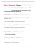
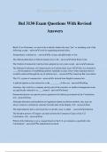
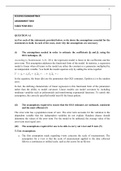
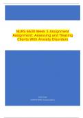
2.0 STRUCTURAL LAYOUTS
,
,
,
,3.0 DESIGN OF STRUCTURAL ELEMENTS
Design Data
Concrete self –weight = 24 kN/m2
Imposed load = 3.0 kN/m2
Finishes =1.5 kN/m2
Characteristic strength of concrete fcu = 30 MPa
Bearing capacity of soil = 150 kPa
Reinforcement bars: fy = 450 MPa
:fyv = 250 MPa
Cover = 25 mm (Slabs, beams and columns),
= 50mm (Foundation)
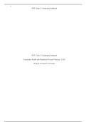
, 3.1 SLAB DESIGN
SANS10100 Consider panel C D 3 4
Loading
Self – weight of slab = 24 x 0.2 = 4.8 kN/m2
Dead load =4.8 + 1.5 = 6.3 kN/m2
n = (1.2 x 6.3) + (1.6 x 3) = 12.36 kN/m2
Aspect ratio ly/lx =5500/3850 = 1.4
This is a two – way spanning slab
4.4.4 Bending moments, 𝒎𝒔 = 𝜷. 𝒏. 𝒍𝟐𝒙
Table 15 Moment coefficients and bending moments
Short span direction
Mid span: m = 0.039 x 12.36 x 3.85 2 = 7.15 kN/m2
Support: m = -0.050 x 12.36 x 3.85 2 = -9.16 kN/m2
Long span direction
Mid span: m = 0.024 x 12.36 x 3.85 2 = 4.40 kN/m2
Support: m = -0.032 x 12.36 x 3.85 2 = -5.86 kN/m2
Assume use of Y16 bars, d = 200 – 25 -16/2 = 167 mm
Design Project
Semester 1 2024
0027 65 934 4052
,TABLE OF CONTENTS
1.0 INTRODUCTION........................................................................................................................... 3
1.1 SCOPE OF THE PROJECT ......................................................................................................... 3
2.0 STRUCTURAL LAYOUTS ........................................................................................................... 3
3.0 DESIGN OF STRUCTURAL ELEMENTS ................................................................................. 7
3.1 SLAB DESIGN ............................................................................................................................. 8
3.2 BEAM DESIGN ......................................................................................................................... 15
3.3 COLUMN DESIGN.................................................................................................................... 20
3.4 FOOTING DESIGN ................................................................................................................... 22
4.0 SOFTWARE APPLICATION ..................................................................................................... 23
4.1 SLAB DESIGN ........................................................................................................................... 23
4.2 BEAM DESIGN ......................................................................................................................... 25
4.3 COLUMN DESIGN.................................................................................................................... 32
4.4 FOOTING DESIGN ................................................................................................................... 44
,1.0 INTRODUCTION
Structural building engineering is primarily driven by creative manipulation of materials and
forms and the underlying mathematical and scientific ideas to achieve an end that fulfils its
functional requirements and is structurally safe when subjected to loading.
1.1 SCOPE OF THE PROJECT
The project focuses on analysis and design of a three -storey office building. The method to be
used in this project is Limit State Design and it involves estimating the subjected loads on a
structure, choosing the sizes of members to check, and selecting the appropriate design criteria.
Limit state design requires that two principal criteria are satisfied: Ultimate limit state and
Serviceability limit state.
2.0 STRUCTURAL LAYOUTS
,
,
,
,3.0 DESIGN OF STRUCTURAL ELEMENTS
Design Data
Concrete self –weight = 24 kN/m2
Imposed load = 3.0 kN/m2
Finishes =1.5 kN/m2
Characteristic strength of concrete fcu = 30 MPa
Bearing capacity of soil = 150 kPa
Reinforcement bars: fy = 450 MPa
:fyv = 250 MPa
Cover = 25 mm (Slabs, beams and columns),
= 50mm (Foundation)
, 3.1 SLAB DESIGN
SANS10100 Consider panel C D 3 4
Loading
Self – weight of slab = 24 x 0.2 = 4.8 kN/m2
Dead load =4.8 + 1.5 = 6.3 kN/m2
n = (1.2 x 6.3) + (1.6 x 3) = 12.36 kN/m2
Aspect ratio ly/lx =5500/3850 = 1.4
This is a two – way spanning slab
4.4.4 Bending moments, 𝒎𝒔 = 𝜷. 𝒏. 𝒍𝟐𝒙
Table 15 Moment coefficients and bending moments
Short span direction
Mid span: m = 0.039 x 12.36 x 3.85 2 = 7.15 kN/m2
Support: m = -0.050 x 12.36 x 3.85 2 = -9.16 kN/m2
Long span direction
Mid span: m = 0.024 x 12.36 x 3.85 2 = 4.40 kN/m2
Support: m = -0.032 x 12.36 x 3.85 2 = -5.86 kN/m2
Assume use of Y16 bars, d = 200 – 25 -16/2 = 167 mm