100% de satisfacción garantizada Inmediatamente disponible después del pago Tanto en línea como en PDF No estas atado a nada
Buscado previamente por ti
Development and test of a mini-Data Acquisition system for the High-Luminosity LHC upgrade of the ATLAS Monitored Drift Tube detector14,41 €
Añadir al carrito
Development and test of a mini-Data Acquisition system for the High-Luminosity LHC upgrade of the ATLAS Monitored Drift Tube detector
2 vistas 0 veces vendidas
Grado
Mini-Data Acquisition
Institución
Mini-Data Acquisition
1. Introduction
The ATLAS detector [1] is a general-purpose particle detector designed to study proton-proton interactions at the
Large Hadron Collider (LHC) at CERN [2]. Its muon spectrometer is designed to trigger and identify muons produced
in collisions and to measure their momenta [3]. Resi...
development and test of a mini data acquisition sy
Escuela, estudio y materia
Mini-Data Acquisition
Vendedor
Seguir
Ariikelsey
Vista previa del contenido
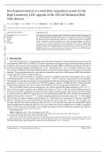
Development and test of a mini-Data Acquisition system for the
High-Luminosity LHC upgrade of the ATLAS Monitored Drift
Tube detector
Yuxiang Guoa , Xueye Hua , Thomas Schwarza , Bing Zhoua and Junjie Zhua
arXiv:2205.13475v1 [physics.ins-det] 26 May 2022
a Department of Physics, University of Michigan, Ann Arbor, MI, 48109, USA
ARTICLE INFO ABSTRACT
Keywords: New front-end electronics including ASICs and FPGA boards are under development for
HL-LHC the ATLAS Monitored Drift Tube (MDT) detector to handle the large data rates and harsh
ATLAS environment expected at high-luminosity LHC runs. A mobile Data Acquisition (miniDAQ)
MDT system is designed to perform integration tests of these front-end electronics. In addition,
miniDAQ it will be used for surface commissioning of 96 small-radius MDT (sMDT) chambers and
for integration and commissioning of new front-end electronics on the present ATLAS MDT
chambers. Details of the miniDAQ hardware and firmware are described in this article. The
miniDAQ system is also used to read out new front-end electronics on an sMDT prototype
chamber using cosmic muons and results obtained are shown.
1. Introduction
The ATLAS detector [1] is a general-purpose particle detector designed to study proton-proton interactions at the
Large Hadron Collider (LHC) at CERN [2]. Its muon spectrometer is designed to trigger and identify muons produced
in collisions and to measure their momenta [3]. Resistive Plate Chambers (RPC) [4] and Thin Gap Chambers (TGC) [5]
are used as fast trigger chambers in the barrel (|𝜂| < 1.05) 1 and endcap (1.05 < |𝜂| < 2.4) regions, respectively. Three
(two) stations of Monitored Drift Tube (MDT) chambers in the barrel (endcap) regions are used as precision-tracking
chambers. The endcap inner station has a new detector composed of eight layers of Micromegas (MM) and eight layers
of small-strip TGC (sTGC) installed in 2021 [6].
The ATLAS muon spectrometer is designed to provide a standalone momentum measurement with a relative
resolution better than 3% over a wide 𝑝𝑇 range and 10% at 𝑝𝑇 = 1 TeV [1], where 𝑝𝑇 is the muon transverse momentum.
The momentum in the muon spectrometer is measured from the deflection of the muon trajectory in the magnetic field
generated by a system of air-core toroid coils. The MDT chambers, together with MM and sTGC, perform precision
charged particle tracking in the transverse plane. Each MDT tube has an average spatial resolution of ∼ 100 𝜇m.
The current MDT readout system was designed to cope with the original LHC design luminosity of 1034 cm−2 s−1
with a first-level trigger acceptance rate of 100 kHz and a latency of 2.5 𝜇s [7]. Hits are stored in buffered memories
of front-end electronics waiting for the ATLAS first-level trigger acceptance signal, while the first-level muon trigger
is exclusively based on RPC/TGC trigger detectors. The high-luminosity LHC (HL-LHC) will have the instantaneous
luminosity increased by a factor of 5 − 7.5 and the integrated luminosity increased by a factor of ∼ 10. The targeted
ATLAS first-level trigger acceptance rate and latency are 1 MHz and 10 𝜇s, respectively [8]. However, each MDT
tube has a diameter of 3 cm and ionized electrons near the tube wall can take up to 750 ns to reach the anode wire,
far longer than the LHC bunch crossing time interval of 25 ns. This long drift time makes the current MDT readout
scheme inappropriate for future HL-LHC runs since a hit is likely to be read out multiple times at 1 MHz. A triggerless
mode to send all muon hits off chambers to new trigger and readout circuitry is preferred. In addition, the relatively
∗ Corresponding author
gyuxiang@umich.edu (Y. Guo); junjie@umich.edu (J. Zhu)
ORCID (s): 0000-0002-6027-5132 (Y. Guo); 0000-0002-3617-290X (X. Hu); 0000-0001-5660-2690 (T. Schwarz);
0000-0002-0034-6576 (B. Zhou); 0000-0002-5278-2855 (J. Zhu)
1 ATLAS uses a right-handed coordinate system with its origin at the nominal interaction point (IP) in the center of the detector and the 𝑧-axis
along the beam pipe. The 𝑥-axis points from the IP to the center of the LHC ring, and the 𝑦-axis points upwards. Cylindrical coordinates (𝑟, 𝜙) are
used in the transverse plane. The pseudorapidity is defined in terms of the polar angle 𝜃 as 𝜂 = − ln tan(𝜃∕2).
Yuxiang Guo et al.: Preprint submitted to Elsevier Page 1 of 10
, Development and test of a mini-Data Acquisition System
long trigger latency allows ATLAS to include MDT chamber data at the first trigger level to improve the trigger muon
momentum resolution and to reject low momentum muons [9].
In addition to upgrading all MDT front-end and back-end electronics, ATLAS also plans to replace part of the
barrel inner station MDT chambers with small-radius MDT (sMDT) chambers. These MDT chambers will have the
tube radius reduced by a factor of 2, to gain space to add an additional layer of RPC chambers in that station to increase
the overall RPC detector coverage [10]. In total 96 new sMDT chambers will be constructed and installed later [11].
Extensive developments are ongoing for the MDT front-end and back-end electronics for the HL-LHC upgrade. A
mobile data acquisition (miniDAQ) system is needed to integrate various front-end electronics prototypes. This system
will also be critical for surface commissioning of these 96 sMDT chambers and for integration and commissioning of
new front-end electronics on the present MDT chambers inside the ATLAS collision hall.
2. The miniDAQ system
2.1. Introduction of the MDT front-end and back-end electronics
Each MDT tube has a diameter of 3 cm and a wall thickness of 400 𝜇m. The central tungsten wire has a diameter
of 50 𝜇m. Tubes are operated with a gas mixture of Ar/CO2 (93%/7%) at 3 bar absolute pressure. For each track, the
electrons from primary ionization clusters drift to the central wire along radial lines. The induced signal propagates
along the wire where it is read out by the MDT front-end electronics. The difference between the earliest arrival time
of the signal at the wire and the reference time provided by trigger chambers gives the drift time of the muon hit, and
this drift time is used to determine the drift radius.
The signal from each tube is first processed by a custom-designed Amplifier/Shaper/Discriminator (ASD)
ASIC [12, 13]. A discriminator is used to determine the signal arrival time, the time when the signal crosses a predefined
threshold. This time depends on the signal pulse height which results in a degradation of the time resolution. The
resolution degradation can partially be recovered by applying a time skew correction using the integrated charge of
the signal pulse. A Wilkinson analog-to-digital converter (ADC) is introduced inside the ASD to integrate the signal
pulse over a predefined integration window of ∼ 20 ns. The total collected charge is measured by the discharge time
of a capacitor by a rundown current. The signal arrival time (also called the leading edge time) and the discharge time
(also called the trailing edge time) are converted into ADC counts using a time-to-digital converter (TDC) ASIC with
a bin size of 0.78 ns [14, 15, 16]. To avoid multiple hits from multiple threshold crossings of a single signal, the ASD
ASIC can be programmed with a dead time of ∼ 1 𝜇s. After the detection of the earliest arrival signal, there are no
additional time measurements performed within this dead time.
Each ASD ASIC can handle 8 tubes and each TDC can handle discriminated signals from three ASDs. A mezzanine
card with three ASDs and one TDC thus handles 24 tubes. A Chamber Service Module (CSM) multiplexes data from
up to 18 mezzanine cards and sends these data via an optical module (VTRx+) [17] to the MDT Trigger Processor [18],
where the relevant hits are extracted out of the raw data stream. Pattern recognition, segment-finding, and track-
fitting algorithms are then applied to determine the muon momentum at the first trigger level. Hit data are stored
for transmission to a network called Front End LInk eXchange (FELIX) [19] after receiving the first-level trigger
acceptance signal.
2.2. Introduction of the miniDAQ system
Due to the new MDT trigger and readout scheme, all front-end and back-end electronics need to be redesigned.
Both ASD and TDC designs have been finished. All ASD chips have been produced, while all TDC chips are expected
to be produced in 2022. The designs for both mezzanine cards and CSM are close to be final and minor modifications
to the current prototypes are expected. The MDT Data Processor is still under development.
It is critical to design a miniDAQ system to integrate these prototype ASICs and boards together and to demonstrate
that the new front-end electronics can run in the triggerless mode to send out all hits. The miniDAQ system is a
lightweight version of the MDT Data Processor. It will send out all matched hits to a PC for storage and pattern
recognition, segment-finding, and track-fitting algorithms will be performed offline. As a result, a low-cost FPGA can
be used and a FELIX system is not needed. The miniDAQ system is expected to be mobile and can be used to study
the performance of new sMDT chambers. It is also expected to be used for the integration and commissioning of new
front-end electronics on the present MDT chambers inside the ATLAS collision hall.
Figure 1 shows the overall miniDAQ readout system planned for a single (s)MDT chamber. Due to the smaller
tube radius, an sMDT chamber can have more than 500 tubes, thus two CSMs are needed to read out all tubes. The
Yuxiang Guo et al.: Preprint submitted to Elsevier Page 2 of 10
Los beneficios de comprar resúmenes en Stuvia estan en línea:
Garantiza la calidad de los comentarios
Compradores de Stuvia evaluaron más de 700.000 resúmenes. Así estas seguro que compras los mejores documentos!
Compra fácil y rápido
Puedes pagar rápidamente y en una vez con iDeal, tarjeta de crédito o con tu crédito de Stuvia. Sin tener que hacerte miembro.
Enfócate en lo más importante
Tus compañeros escriben los resúmenes. Por eso tienes la seguridad que tienes un resumen actual y confiable.
Así llegas a la conclusión rapidamente!
Preguntas frecuentes
What do I get when I buy this document?
You get a PDF, available immediately after your purchase. The purchased document is accessible anytime, anywhere and indefinitely through your profile.
100% de satisfacción garantizada: ¿Cómo funciona?
Nuestra garantía de satisfacción le asegura que siempre encontrará un documento de estudio a tu medida. Tu rellenas un formulario y nuestro equipo de atención al cliente se encarga del resto.
Who am I buying this summary from?
Stuvia is a marketplace, so you are not buying this document from us, but from seller Ariikelsey. Stuvia facilitates payment to the seller.
Will I be stuck with a subscription?
No, you only buy this summary for 14,41 €. You're not tied to anything after your purchase.