Chapter 1: Routing Concepts
The router is responsible for the delivery of packets across different networks. The router
uses its routing table to determine the best path to use to forward a packet. It is the
responsibility of the routers to deliver those packets in a timely manner.
The default gateway is the destination that routes traffic from the local network to devices
on remote networks.
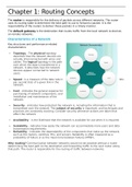
Characteristics of a Network
Key structures and performance-related
characteristics:
Topology - The physical topology
describes how the network devices are
actually interconnected with wires and
cables. The logical topology is the path
over which the data is transferred in a
network. It describes how the network
devices appear connected to network
users.
Speed - is a measure of the data rate in bits
per second (b/s) of a given link in the
network.
Cost - indicates the general expense for
purchasing of network components, and
installation and maintenance of the
network.
Security - indicates how protected the network is, including the information that is
transmitted over the network. The subject of security is important, and techniques and
practices are constantly evolving. Consider security whenever actions are taken that
affect the network.
Availability - is the likelihood that the network is available for use when it is required.
Scalability - indicates how easily the network can accommodate more users and data
transmission requirements.
Reliability - indicates the dependability of the components that make up the network,
such as the routers, switches, PCs, and servers. Reliability is often measured as a
probability of failure or as the mean time between failures (MTBF).
Why routing? Communication between networks would not be possible without a router
determining the best path to the destination and forwarding traffic to the next router along
that path. The router is responsible for the routing of traffic between networks.
,The primary functions of a router are to:
Determine the best path to send packets
Forward packets toward their destination
It is the responsibility of the router to find the destination network in its routing table and
forward the packet on toward its destination.
The routing table also includes the interface to be used to forward packets for each known
network. When a match is found, the router encapsulates the packet into the data link frame
of the outgoing or exit interface, and the packet is forwarded toward its destination.
It is possible for a router to receive a packet that is encapsulated in one type of data link
frame, and to forward the packet out of an interface that uses a different type of data link
frame.
,Packet Forwarding Mechanisms
Routers support three packet-forwarding
mechanisms:
Process switching (old) - When a packet
arrives on an interface, it is forwarded to the
control plane where the CPU matches the
destination address with an entry in its
routing table, and then determines the exit
interface and forwards the packet. It is
important to understand that the router does
this for every packet, even if the destination
is the same for a stream of packets. This
process-switching mechanism is very slow and rarely implemented in modern networks.
Fast switching - This is a common packet
forwarding mechanism which uses a fast-
switching cache to store next-hop
information. When a packet arrives on an
interface, it is forwarded to the control plane
where the CPU searches for a match in the
fast-switching cache. If it is not there, it is
process-switched and forwarded to the exit
interface. The flow information for the packet
is also stored in the fast-switching cache. If
another packet going to the same destination
arrives on an interface, the next-hop information in the cache is re-used without CPU
intervention.
Cisco Express Forwarding (CEF, most
recent & preferred) - Like fast switching, CEF
builds a Forwarding Information Base (FIB),
and an adjacency table. However, the table
entries are not packet-triggered like fast
switching but change-triggered such as when
something changes in the network topology.
Therefore, when a network has converged,
the FIB and adjacency tables contain all the
information a router would have to consider
when forwarding a packet. The FIB contains
pre-computed reverse lookups, next hop
information for routes including the interface and Layer 2 information.
A common analogy used to describe the three packet-forwarding mechanisms is as follows:
Process switching solves a problem by doing math long hand, even if it is the
identical problem.
Fast switching solves a problem by doing math long hand one time and remembering
the answer for subsequent identical problems.
CEF solves every possible problem ahead of time in a spreadsheet.
Connect Devices
To enable network access, devices must be configured with IP address information to identify
the appropriate:
IP address - Identifies a unique host on a local network.
Subnet mask - Identifies with which network subnet the host can communicate.
, Default gateway - Identifies the IP address of the router to send a packet to when the
destination is not on the same local network subnet.
When a host sends a packet to a device on a different IP network, then the packet is
forwarded to the default gateway, because a host device cannot communicate directly with
devices outside of the local network. The default gateway is the destination that routes traffic
from the local network to devices on remote networks. It is often used to connect a local
network to the Internet.
A router is also usually configured with its own default gateway = Gateway of Last Resort.
Two useful network documents:
Topology diagram - Provides a visual reference that indicates the physical
connectivity and logical Layer 3 addressing. Often created using software, such as
Microsoft Visio.
An addressing table - A table that captures device names, interfaces, IPv4 addresses,
subnet masks, and default gateway addresses.
A host can be assigned IP address information either:
Statically - The host is manually assigned the correct IP address, subnet mask, and
default gateway. The DNS server IP address can also be configured.
Dynamically - IP address information is provided by a server using the Dynamic Host
Configuration Protocol (DHCP). The DHCP server provides a valid IP address, subnet
mask, and default gateway for end devices. Other information may be provided by the
server.
Host computers connect to a wired network using a network interface and RJ-45 Ethernet
cable. Most network interfaces have one or two LED link indicators next to the interface.
Typically, a green LED means a good connection while a blinking green LED indicates network
activity.
If the link light is not on, then there may be a problem with either the network cable or the
network itself. The switch port where the connection terminates would also have an LED
indicator lit. If one or both ends are not lit, try a different network cable.
Console access requires:
Console cable - RJ-45-to-DB-9 serial cable or a USB serial cable
Terminal emulation software - Tera Term, PuTTY, HyperTerminal
The cable is connected between the serial port of the host and the console port on the device.
If the host does not have a serial port, the USB port can be used to establish a console
connection. A special USB-to-RS-232 compatible serial port adapter is required when using the
USB port.
Router Basic Settings
Enable IP on a Switch
A switch does not have a dedicated interface
to which an IP address can be assigned.
Instead, the IP address information is
configured on a virtual interface called a
switched virtual interface (SVI).
One distinguishing feature between switches and routers is the type of interfaces supported
by each.