See discussions, stats, and author profiles for this publication at: https://www.researchgate.net/publication/300857212
Gas Turbine Working Principles
Chapter · March 2015
DOI: 10.1007/978-3-319-15560-9_7
CITATIONS READS
7 175,529
1 author:
Bahman Zohuri
Galaxy Advanced Engineering
578 PUBLICATIONS 2,093 CITATIONS
SEE PROFILE
Some of the authors of this publication are also working on these related projects:
Business Resilience System (BRS): Driven Through Boolean, Fuzzy Logics and Cloud Computation: Real and Near Real Time Analysis and Decision Making System View
project
I am working on cloud computation and mathematical modeling of Fuzzy logic in cloud data warehousing and datamining View project
All content following this page was uploaded by Bahman Zohuri on 20 August 2018.
The user has requested enhancement of the downloaded file.
,Chapter 7
Gas Turbine Working Principals
Gas turbine engines derive their power from burning fuel in a combustion chamber
and using the fast-flowing combustion gases to drive a turbine in much the same
way as the high-pressure steam drives a steam turbine. A simple gas turbine is
comprised of three main sections: a compressor, a combustor, and a power turbine.
The gas turbine operates on the principle of the Brayton cycle, where compressed
air is mixed with fuel and burned under constant pressure conditions. The resulting
hot gas is allowed to expand through a turbine to perform work.
7.1 Introduction
As the principle of the gas turbine, a working gas (air) is compressed by a
compressor and heated by combustion energy of the fuel at the first. The working
gas becomes the high temperature and high pressure. The engine converts the
energy of working gas into the rotating energy of the blades, making use of the
interaction between the gas and the blades.
As shown in the below figure, there are two types of gas turbine. One is the open
cycle type (internal type) and another is the closed cycle type (external type). Basic
components of both types are the air compressor, a combustor, and the turbine.
The gas turbine can handle a larger gas flow than that of the reciprocating
internal combustion engines, because it utilizes a continued combustion. Then the
gas turbine is suitable as the high power engine. The gas turbine for airplanes
(called a jet engine) makes use of this advantage.
As we said at the beginning of this chapter, the gas turbine operates on the
principle of the Brayton cycle and one variation of this basic cycle is the addition of
a regenerator. A gas turbine with a regenerator (heat exchanger) recaptures some of
the energy in the exhaust gas, preheating the air entering the combustor. This cycle
is typically used on low-pressure ratio turbines, and the resulting hot gas is allowed
to expand through a turbine to perform work. In a 33% efficient gas turbine, almost
© Springer International Publishing AG 2018 149
B. Zohuri, P. McDaniel, Combined Cycle Driven Efficiency for Next Generation
Nuclear Power Plants, https://doi.org/10.1007/978-3-319-70551-4_7
, 150 7 Gas Turbine Working Principals
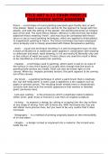
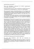
GAS-TURBINE WITH REGENERATION
FUEL
COMBUSTOR
INLET AIR
COMPRESSED
AIR
HOT
PREHEATED GAS
COMPRESSOR AIR
POWER TURBINE
EHAUST
GAS
Fig. 7.1 Schematic of solar centaur/3500 horsepower class (Courtesy of general electric)
2/3 of this work is spent compressing the air; the rest is available for other work
such as mechanical drive or electrical generation. Figure 7.1 is schematic of such
principle.
Gas turbines with high-pressure ratios can use an intercooler to cool the air
between stages of compression, allowing you to burn more fuel and generate more
power. Remember, the limiting factor on fuel input is the temperature of the hot gas
created, because of the metallurgy of the first stage nozzle and turbine blades. With
the advances in materials technology, this physical limit is always climbing.
Figures. 7.2 and 7.3 are illustrations of a gas turbine, using an intercooling (heat
exchanger), while Fig. 7.4 is presenting a gas turbine with reheater.
The gas turbine can handle a larger gas flow than that of the reciprocating
internal combustion engines, because it utilizes a continued combustion. Then the
gas turbine is suitable as the high power engine. The gas turbine for airplanes
(called a jet engine) makes use of this advantage.
Generally speaking gas turbine is divided into two categories as follows:
1. Open cycle gas turbine
2. Closed cycle gas turbine
Both of these two cycles are presented in Fig. 7.5.
In case of jet engine power plant, as we said, they drive their power from burning
fuel in a combustion chamber and using the fast-flowing combustion gases to drive
a turbine in much the same way as the high-pressure steam drives a steam turbine.
See Fig. 7.6.
Gas Turbine Working Principles
Chapter · March 2015
DOI: 10.1007/978-3-319-15560-9_7
CITATIONS READS
7 175,529
1 author:
Bahman Zohuri
Galaxy Advanced Engineering
578 PUBLICATIONS 2,093 CITATIONS
SEE PROFILE
Some of the authors of this publication are also working on these related projects:
Business Resilience System (BRS): Driven Through Boolean, Fuzzy Logics and Cloud Computation: Real and Near Real Time Analysis and Decision Making System View
project
I am working on cloud computation and mathematical modeling of Fuzzy logic in cloud data warehousing and datamining View project
All content following this page was uploaded by Bahman Zohuri on 20 August 2018.
The user has requested enhancement of the downloaded file.
,Chapter 7
Gas Turbine Working Principals
Gas turbine engines derive their power from burning fuel in a combustion chamber
and using the fast-flowing combustion gases to drive a turbine in much the same
way as the high-pressure steam drives a steam turbine. A simple gas turbine is
comprised of three main sections: a compressor, a combustor, and a power turbine.
The gas turbine operates on the principle of the Brayton cycle, where compressed
air is mixed with fuel and burned under constant pressure conditions. The resulting
hot gas is allowed to expand through a turbine to perform work.
7.1 Introduction
As the principle of the gas turbine, a working gas (air) is compressed by a
compressor and heated by combustion energy of the fuel at the first. The working
gas becomes the high temperature and high pressure. The engine converts the
energy of working gas into the rotating energy of the blades, making use of the
interaction between the gas and the blades.
As shown in the below figure, there are two types of gas turbine. One is the open
cycle type (internal type) and another is the closed cycle type (external type). Basic
components of both types are the air compressor, a combustor, and the turbine.
The gas turbine can handle a larger gas flow than that of the reciprocating
internal combustion engines, because it utilizes a continued combustion. Then the
gas turbine is suitable as the high power engine. The gas turbine for airplanes
(called a jet engine) makes use of this advantage.
As we said at the beginning of this chapter, the gas turbine operates on the
principle of the Brayton cycle and one variation of this basic cycle is the addition of
a regenerator. A gas turbine with a regenerator (heat exchanger) recaptures some of
the energy in the exhaust gas, preheating the air entering the combustor. This cycle
is typically used on low-pressure ratio turbines, and the resulting hot gas is allowed
to expand through a turbine to perform work. In a 33% efficient gas turbine, almost
© Springer International Publishing AG 2018 149
B. Zohuri, P. McDaniel, Combined Cycle Driven Efficiency for Next Generation
Nuclear Power Plants, https://doi.org/10.1007/978-3-319-70551-4_7
, 150 7 Gas Turbine Working Principals
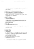
GAS-TURBINE WITH REGENERATION
FUEL
COMBUSTOR
INLET AIR
COMPRESSED
AIR
HOT
PREHEATED GAS
COMPRESSOR AIR
POWER TURBINE
EHAUST
GAS
Fig. 7.1 Schematic of solar centaur/3500 horsepower class (Courtesy of general electric)
2/3 of this work is spent compressing the air; the rest is available for other work
such as mechanical drive or electrical generation. Figure 7.1 is schematic of such
principle.
Gas turbines with high-pressure ratios can use an intercooler to cool the air
between stages of compression, allowing you to burn more fuel and generate more
power. Remember, the limiting factor on fuel input is the temperature of the hot gas
created, because of the metallurgy of the first stage nozzle and turbine blades. With
the advances in materials technology, this physical limit is always climbing.
Figures. 7.2 and 7.3 are illustrations of a gas turbine, using an intercooling (heat
exchanger), while Fig. 7.4 is presenting a gas turbine with reheater.
The gas turbine can handle a larger gas flow than that of the reciprocating
internal combustion engines, because it utilizes a continued combustion. Then the
gas turbine is suitable as the high power engine. The gas turbine for airplanes
(called a jet engine) makes use of this advantage.
Generally speaking gas turbine is divided into two categories as follows:
1. Open cycle gas turbine
2. Closed cycle gas turbine
Both of these two cycles are presented in Fig. 7.5.
In case of jet engine power plant, as we said, they drive their power from burning
fuel in a combustion chamber and using the fast-flowing combustion gases to drive
a turbine in much the same way as the high-pressure steam drives a steam turbine.
See Fig. 7.6.