BRIEFING IRI
09 The precision approach
AS PER Acceptable Means of Compliance and Guidance Material to
Part-FCL 1 AMC1 FCL.930.IRI IRI— Training Course / Long Briefings and Air
Exercises: Exercise 10: Instrument Approach: ILS Approaches to Specified Minima and
Missed Approach Procedure (P454)
2 TYPES of PRECISION APPROACHES 3
INSTRUMENT LANDING SYSTEMS (ILS) 3
ILS COMPONENTS 4
• Localizer 4
• Glide slope (GS) 6
o The typical VOR/ILS receiver 8
o Inoperative ILS Components 9
o ILS Course Distortion 9
• Marker 10
• Approach lights 12
SUPPLEMENTARY ELEMENTS 19
• Compass locators 19
• DME collocated 20
ILS APPROACHES CATEGORIES 21
INITIAL/INTERMEDIATE/FINAL APPROACH PROCEDURES 22
• Precision approach charts 22
• Approach to the initial approach fix 24
• Before IAF: 25
• Minimum sector/safe altitude (MSA) 26
• Navaid requirements, e.g. radar, ADF, etc. 26
• Communication (ATC liaison and R/T phraseology) 27
• Holding procedure 29
• Completion of aerodrome approach checks 29
• Forming a mental picture of the approach 30
• Assessment of distance, groundspeed time, and rate of
descent from the final approach fix to the aerodrome 31
• The final approach track 32
• Obstacle clearance altitude/height 33
o DA and MDA computation 34
o The Obstruction Heights to be borne in mind during
Visual maneuvering after an Instrument Approach 35
• Operating Minima 36
o Weather Consideration, e.g. Cloud Base and Visibility 36
o Approach Ban 36
o MET Visibility / RVR Conversion 36
Briefings IRI 09 ILS APP REV03: MAY 22 Page 1
, o Failed or downgraded equipment (EU-ops 1) 37
• Achieving the horizontal and vertical patterns 38
• Use of DME 39
• ILS Entry Methods 40
• Radar Vectors 40
• Procedural Method 40
• At the Final Approach Fix 41
• Maintaining the Localizer and Glide Path 41
o The Descent Rate on Final Approach 41
o Anticipation in Change of Wind Velocity and direction &
its Effect on Drift 41
o Tracking 41
• at OM: ALTI check 41
o temperature correction 41
• + 500 FT 42
• Stabilized Approach Procedure 42
• Decision Height 43
o Availability of Runway Lighting 43
o 200 Ft Above 43
o 100 Ft above 43
o DA 43
o Go around 43
o Visual References 44
• Runway Direction 44
• Transition from instr. to visual flight (sensory illusions) 45
GO AROUND AND MISSED APPROACH PROCEDURE 49
• Review of the published instructions 50
VISUAL MANOEUVRING AFTER AN INSTRUMENT APPROACH 51
• Visual Approach to Landing 51
• Circling Approach 52
CONCLUSIONS 53
• C182 checklist & procedures for ILS 53
• Next Step Concept 53
THE LOCALIZER APPROACH 56
LOCALIZER BACK COURSE 56
LOCALIZER-TYPE DIRECTIONAL AID 57
THE SIMPLIFIED DIRECTIONAL FACILITY (SDF) 58
Briefings IRI 09 ILS APP REV03: MAY 22 Page 2
,2 TYPES OF PRECISION APPROACHES
- ILS (Instrument Landing System)
- PAR (Precision Approach Radar): will be seen in another Briefing
(Briefings IRI 12 SRA GCA)
INSTRUMENT LANDING SYSTEMS (ILS)
(Radio Aids 1-1-9)
a. General
1. The ILS is designed to provide an approach path for exact alignment and descent of
an aircraft on final approach to a runway.
2. The ground equipment consists of two highly directional transmitting systems and,
along the approach, three (or fewer) marker beacons. The directional transmitters are
known as the localizer and glide slope transmitters.
Briefings IRI 09 ILS APP REV03: MAY 22 Page 3
,ILS Components
3. The system may be divided functionally into three parts:
(a) Guidance information: localizer, glide slope;
(b) Range information: marker beacon, DME;
(c) Visual information: approach lights, touchdown and centerline lights, runway
lights.
+ Supplementary elements:
4. Precision radar, or compass locators located at the Outer Marker (OM) or Middle
Marker (MM), may be substituted for marker beacons.
DME, when specified in the procedure, may be substituted for the OM.
5. Where a complete ILS system is installed on each end of a runway; (i.e., the
approach end of Runway 4 and the approach end of Runway 22) the ILS systems are
not in service simultaneously.
How it is noted on charts:
Guidance information
b. Localizer
1. The localizer transmitter operates on one of 40 ILS channels within the frequency
range of 108.10 to 111.95 MHz (Ed’ notes : odd tenths only).
Signals provide the pilot with course guidance to the runway centerline.
2. The approach course of the localizer is called the front course and is used with other
functional parts, e.g., glide slope, marker beacons, etc. The localizer signal is
transmitted at the far end of the runway. It is adjusted for a course width of (full scale
fly-left to a full scale fly-right) of 700 feet at the runway threshold.
Briefings IRI 09 ILS APP REV03: MAY 22 Page 4
, 3. The course line along the extended centerline of a runway, in the opposite direction
to the front course is called the back course.
CAUTION: Unless the aircraft’s ILS equipment includes reverse sensing
capability, when flying inbound on the back course it is necessary to steer the
aircraft in the direction opposite the needle deflection when making corrections
from off-course to on-course.
This “flying away from the needle” is also required when flying outbound on
the front course of the localizer. Do not use back course signals for approach
unless a back course approach procedure is published for that particular
runway and the approach is authorized by ATC.
4. Identification is in International Morse Code and consists of a three-letter identifier
preceded by the letter I (••) transmitted on the localizer frequency.
EXAMPLE: I-DIA
(Ed’ note: not always 3, could be two only.
For example, the ILS localizer at Charleroi
transmits the identifier IGC)
(Ed’ note: OBS: not really necessary as no
influence but useful due to QFU info !)
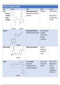
5. The localizer provides course guidance
throughout the descent path to the runway
threshold from a distance of 18 NM from the
antenna between an altitude of 1,000 feet
above the highest terrain along the course
line and 4,500 feet above the elevation of the
antenna site. Proper off-course indications
are provided throughout the following
angular areas of the operational service
volume:
(a) To 10 degrees either side of the course
along a radius of 18 NM from the antenna;
and
(b) From 10 to 35 degrees either side of the course along a radius of 10 NM.
6. Unreliable signals may be received outside these areas.
Briefings IRI 09 ILS APP REV03: MAY 22 Page 5
, Guidance information
d. Glide Slope/Glide Path
1. The UHF glide slope transmitter, operating on one of the 40
ILS channels within the frequency range 329.15 MHz, to 335.00
MHz radiates its signals in the direction of the localizer front
course. The term “glide path” means that portion of the glide
slope that intersects the localizer.
CAUTION: False glide slope
signals may exist in the area
of the localizer back course
approach which can cause the
glide slope flag alarm to
disappear and present
unreliable glide slope
information. Disregard all
glide slope signal indications
when making a localizer back
course approach unless a
glide slope is specified on the
approach and landing chart.
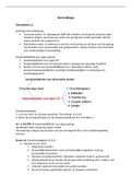
2. The glide slope transmitter is located between 750 feet and 1,250 feet from the
approach end of the runway (down the runway) and offset 250 to 650 feet from the
runway centerline.
It transmits a glide path beam 1.4 degrees wide (vertically).
The signal provides descent
information for navigation down
to the lowest authorized decision
height (DH) specified in the
approved ILS approach procedure.
The glidepath may not be suitable
for navigation below the lowest
authorized DH and any reference
to glidepath indications below that
height must be supplemented by
visual reference to the runway
environment. Glidepaths with no
published DH are usable to
runway threshold.
3. The glide path projection angle is normally adjusted to 3 degrees above horizontal
so that it intersects the MM at about 200 feet and the OM at about 1,400 feet above the
runway elevation. The glide slope is normally usable to the distance of 10 NM.
However, at some locations, the
glide slope has been certified for
an extended service volume
which exceeds 10 NM.
Briefings IRI 09 ILS APP REV03: MAY 22 Page 6
, 4. Pilots must be alert when approaching the glidepath interception. False courses and
reverse sensing will occur at angles considerably greater than the published path.
5. Make every effort to remain on the indicated glide path.
CAUTION: Avoid flying below the glide path to assure obstacle/terrain
clearance is maintained.
6. The published glide slope threshold crossing height (TCH) DOES NOT
represent the height of the actual glide path on-course indication above
the runway threshold. It is used as a reference for planning purposes which
represents the height above the runway threshold that aircraft’s glideslope
antenna SHOULD BE, if that aircraft remains on a trajectory formed by the four-
mile-to-middle marker glidepath segment.
7. Pilots must be aware of the vertical height between the aircraft’s glide slope antenna
and the main gear in the landing configuration and, at the DH, plan to adjust the
descent angle accordingly if the published TCH indicates the wheel crossing height
over the runway threshold may not be satisfactory. Tests indicate a comfortable wheel
crossing height is approximately 20 to 30 feet, depending on the type of aircraft.
NOTE: The TCH for a runway is established based on several factors including
the largest aircraft category that normally uses the runway, how airport layout
effects the glide slope antenna placement, and terrain. A higher than optimum
TCH, with the same glide path angle, may cause the aircraft to touch down
further from the threshold if the trajectory of the approach is maintained until
the flare. Pilots should consider the effect of a high TCH on the runway
available for stopping the aircraft.
Briefings IRI 09 ILS APP REV03: MAY 22 Page 7
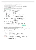
,The typical VOR/ILS receiver
Is also a localizer receiver with common tuning and indicating equipment.
Tuning of VOR and localizer frequencies is accomplished with the same knobs and switches,
and the CDI indicates “on course” as it does on a VOR radial.
• When the aircraft is on the
glide path, the needle is
horizontal, overlying the
reference dots.
• The localizer and GS
warning flags disappear
from view on the indicator
when sufficient voltage is
received to actuate the
needles.
• The flags show when an
unstable signal or receiver
malfunction occurs.
Briefings IRI 09 ILS APP REV03: MAY 22 Page 8
,j. Inoperative ILS Components
1. Inop localizer. When the LOC fails, an ILS approach is not authorized.
2. Inoperative glideslope. When the glide slope fails, ILS reverts to a non-
precision localizer app.
But during training the best is to go-around, and then shoot a loc app!
k. ILS Course Distortion
1. All pilots should be aware that disturbances to ILS localizer and glide slope
courses may occur when surface vehicles or aircraft (authors’ note: also
airborne) are operated near localizer or glideslope antennas. Most ILS
installations are subject to signal interference by surface vehicles, aircraft or
both. ILS CRITICAL AREAS are established near each localizer and glide slope
antenna.
2. ATC issues control instructions to avoid interfering operations within ILS critical
areas at controlled airports during the hours the Airport Traffic Control Tower
(ATCT) is in operation as follows:
(a) Weather Conditions.
Less than ceiling 800 feet and/or visibility 2 miles.
(1) Localizer Critical Area. Except for aircraft that land, exit a runway, depart
or miss approach, vehicles and aircraft are not authorized in or over the
critical area when an arriving aircraft is between the ILS final approach fix
and the airport. Additionally, when the ceiling is less than 200 feet and/or the
visibility is RVR 2,000 or less, vehicle and aircraft operations in or over the
area are not authorized when an arriving aircraft is inside the ILS MM.
(2) Glide Slope Critical Area. Vehicles and aircraft are not authorized in the
area when an arriving aircraft is between the ILS final approach fix and the
airport unless the aircraft has reported the airport in sight and is circling or
sidestepping to land on a runway other than the ILS runway.
(b) Weather Conditions.
At or above ceiling 800 feet and/or visibility 2 miles.
(1) No critical area protective action is provided under these conditions.
EXAMPLE: Glideslope signal not protected.
3. Aircraft holding below 5,000 feet between the outer marker and the airport may
cause localizer signal variations for aircraft conducting the ILS approach.
Accordingly, such holding is not authorized when weather or visibility conditions
are less than ceiling 800 feet and/or visibility 2 miles.
4. Pilots are cautioned that vehicular traffic not subject to ATC may cause
momentary deviation to ILS course or glide slope signals. Also, critical areas
are not protected at uncontrolled airports or at airports with an operating control
tower when weather or visibility conditions are above those requiring protective
measures. Aircraft conducting coupled or autoland operations should be
especially alert in monitoring automatic flight control systems.
NOTE: Unless otherwise coordinated through Flight Standards, ILS signals to
Category I runways are not flight inspected below 100 feet AGL. Guidance
signal anomalies may be encountered below this altitude.
Briefings IRI 09 ILS APP REV03: MAY 22 Page 9
, Range information
3. Marker beacons providing range information along the approach path.
Briefings IRI 09 ILS APP REV03: MAY 22 Page 10
09 The precision approach
AS PER Acceptable Means of Compliance and Guidance Material to
Part-FCL 1 AMC1 FCL.930.IRI IRI— Training Course / Long Briefings and Air
Exercises: Exercise 10: Instrument Approach: ILS Approaches to Specified Minima and
Missed Approach Procedure (P454)
2 TYPES of PRECISION APPROACHES 3
INSTRUMENT LANDING SYSTEMS (ILS) 3
ILS COMPONENTS 4
• Localizer 4
• Glide slope (GS) 6
o The typical VOR/ILS receiver 8
o Inoperative ILS Components 9
o ILS Course Distortion 9
• Marker 10
• Approach lights 12
SUPPLEMENTARY ELEMENTS 19
• Compass locators 19
• DME collocated 20
ILS APPROACHES CATEGORIES 21
INITIAL/INTERMEDIATE/FINAL APPROACH PROCEDURES 22
• Precision approach charts 22
• Approach to the initial approach fix 24
• Before IAF: 25
• Minimum sector/safe altitude (MSA) 26
• Navaid requirements, e.g. radar, ADF, etc. 26
• Communication (ATC liaison and R/T phraseology) 27
• Holding procedure 29
• Completion of aerodrome approach checks 29
• Forming a mental picture of the approach 30
• Assessment of distance, groundspeed time, and rate of
descent from the final approach fix to the aerodrome 31
• The final approach track 32
• Obstacle clearance altitude/height 33
o DA and MDA computation 34
o The Obstruction Heights to be borne in mind during
Visual maneuvering after an Instrument Approach 35
• Operating Minima 36
o Weather Consideration, e.g. Cloud Base and Visibility 36
o Approach Ban 36
o MET Visibility / RVR Conversion 36
Briefings IRI 09 ILS APP REV03: MAY 22 Page 1
, o Failed or downgraded equipment (EU-ops 1) 37
• Achieving the horizontal and vertical patterns 38
• Use of DME 39
• ILS Entry Methods 40
• Radar Vectors 40
• Procedural Method 40
• At the Final Approach Fix 41
• Maintaining the Localizer and Glide Path 41
o The Descent Rate on Final Approach 41
o Anticipation in Change of Wind Velocity and direction &
its Effect on Drift 41
o Tracking 41
• at OM: ALTI check 41
o temperature correction 41
• + 500 FT 42
• Stabilized Approach Procedure 42
• Decision Height 43
o Availability of Runway Lighting 43
o 200 Ft Above 43
o 100 Ft above 43
o DA 43
o Go around 43
o Visual References 44
• Runway Direction 44
• Transition from instr. to visual flight (sensory illusions) 45
GO AROUND AND MISSED APPROACH PROCEDURE 49
• Review of the published instructions 50
VISUAL MANOEUVRING AFTER AN INSTRUMENT APPROACH 51
• Visual Approach to Landing 51
• Circling Approach 52
CONCLUSIONS 53
• C182 checklist & procedures for ILS 53
• Next Step Concept 53
THE LOCALIZER APPROACH 56
LOCALIZER BACK COURSE 56
LOCALIZER-TYPE DIRECTIONAL AID 57
THE SIMPLIFIED DIRECTIONAL FACILITY (SDF) 58
Briefings IRI 09 ILS APP REV03: MAY 22 Page 2
,2 TYPES OF PRECISION APPROACHES
- ILS (Instrument Landing System)
- PAR (Precision Approach Radar): will be seen in another Briefing
(Briefings IRI 12 SRA GCA)
INSTRUMENT LANDING SYSTEMS (ILS)
(Radio Aids 1-1-9)
a. General
1. The ILS is designed to provide an approach path for exact alignment and descent of
an aircraft on final approach to a runway.
2. The ground equipment consists of two highly directional transmitting systems and,
along the approach, three (or fewer) marker beacons. The directional transmitters are
known as the localizer and glide slope transmitters.
Briefings IRI 09 ILS APP REV03: MAY 22 Page 3
,ILS Components
3. The system may be divided functionally into three parts:
(a) Guidance information: localizer, glide slope;
(b) Range information: marker beacon, DME;
(c) Visual information: approach lights, touchdown and centerline lights, runway
lights.
+ Supplementary elements:
4. Precision radar, or compass locators located at the Outer Marker (OM) or Middle
Marker (MM), may be substituted for marker beacons.
DME, when specified in the procedure, may be substituted for the OM.
5. Where a complete ILS system is installed on each end of a runway; (i.e., the
approach end of Runway 4 and the approach end of Runway 22) the ILS systems are
not in service simultaneously.
How it is noted on charts:
Guidance information
b. Localizer
1. The localizer transmitter operates on one of 40 ILS channels within the frequency
range of 108.10 to 111.95 MHz (Ed’ notes : odd tenths only).
Signals provide the pilot with course guidance to the runway centerline.
2. The approach course of the localizer is called the front course and is used with other
functional parts, e.g., glide slope, marker beacons, etc. The localizer signal is
transmitted at the far end of the runway. It is adjusted for a course width of (full scale
fly-left to a full scale fly-right) of 700 feet at the runway threshold.
Briefings IRI 09 ILS APP REV03: MAY 22 Page 4
, 3. The course line along the extended centerline of a runway, in the opposite direction
to the front course is called the back course.
CAUTION: Unless the aircraft’s ILS equipment includes reverse sensing
capability, when flying inbound on the back course it is necessary to steer the
aircraft in the direction opposite the needle deflection when making corrections
from off-course to on-course.
This “flying away from the needle” is also required when flying outbound on
the front course of the localizer. Do not use back course signals for approach
unless a back course approach procedure is published for that particular
runway and the approach is authorized by ATC.
4. Identification is in International Morse Code and consists of a three-letter identifier
preceded by the letter I (••) transmitted on the localizer frequency.
EXAMPLE: I-DIA
(Ed’ note: not always 3, could be two only.
For example, the ILS localizer at Charleroi
transmits the identifier IGC)
(Ed’ note: OBS: not really necessary as no
influence but useful due to QFU info !)
5. The localizer provides course guidance
throughout the descent path to the runway
threshold from a distance of 18 NM from the
antenna between an altitude of 1,000 feet
above the highest terrain along the course
line and 4,500 feet above the elevation of the
antenna site. Proper off-course indications
are provided throughout the following
angular areas of the operational service
volume:
(a) To 10 degrees either side of the course
along a radius of 18 NM from the antenna;
and
(b) From 10 to 35 degrees either side of the course along a radius of 10 NM.
6. Unreliable signals may be received outside these areas.
Briefings IRI 09 ILS APP REV03: MAY 22 Page 5
, Guidance information
d. Glide Slope/Glide Path
1. The UHF glide slope transmitter, operating on one of the 40
ILS channels within the frequency range 329.15 MHz, to 335.00
MHz radiates its signals in the direction of the localizer front
course. The term “glide path” means that portion of the glide
slope that intersects the localizer.
CAUTION: False glide slope
signals may exist in the area
of the localizer back course
approach which can cause the
glide slope flag alarm to
disappear and present
unreliable glide slope
information. Disregard all
glide slope signal indications
when making a localizer back
course approach unless a
glide slope is specified on the
approach and landing chart.
2. The glide slope transmitter is located between 750 feet and 1,250 feet from the
approach end of the runway (down the runway) and offset 250 to 650 feet from the
runway centerline.
It transmits a glide path beam 1.4 degrees wide (vertically).
The signal provides descent
information for navigation down
to the lowest authorized decision
height (DH) specified in the
approved ILS approach procedure.
The glidepath may not be suitable
for navigation below the lowest
authorized DH and any reference
to glidepath indications below that
height must be supplemented by
visual reference to the runway
environment. Glidepaths with no
published DH are usable to
runway threshold.
3. The glide path projection angle is normally adjusted to 3 degrees above horizontal
so that it intersects the MM at about 200 feet and the OM at about 1,400 feet above the
runway elevation. The glide slope is normally usable to the distance of 10 NM.
However, at some locations, the
glide slope has been certified for
an extended service volume
which exceeds 10 NM.
Briefings IRI 09 ILS APP REV03: MAY 22 Page 6
, 4. Pilots must be alert when approaching the glidepath interception. False courses and
reverse sensing will occur at angles considerably greater than the published path.
5. Make every effort to remain on the indicated glide path.
CAUTION: Avoid flying below the glide path to assure obstacle/terrain
clearance is maintained.
6. The published glide slope threshold crossing height (TCH) DOES NOT
represent the height of the actual glide path on-course indication above
the runway threshold. It is used as a reference for planning purposes which
represents the height above the runway threshold that aircraft’s glideslope
antenna SHOULD BE, if that aircraft remains on a trajectory formed by the four-
mile-to-middle marker glidepath segment.
7. Pilots must be aware of the vertical height between the aircraft’s glide slope antenna
and the main gear in the landing configuration and, at the DH, plan to adjust the
descent angle accordingly if the published TCH indicates the wheel crossing height
over the runway threshold may not be satisfactory. Tests indicate a comfortable wheel
crossing height is approximately 20 to 30 feet, depending on the type of aircraft.
NOTE: The TCH for a runway is established based on several factors including
the largest aircraft category that normally uses the runway, how airport layout
effects the glide slope antenna placement, and terrain. A higher than optimum
TCH, with the same glide path angle, may cause the aircraft to touch down
further from the threshold if the trajectory of the approach is maintained until
the flare. Pilots should consider the effect of a high TCH on the runway
available for stopping the aircraft.
Briefings IRI 09 ILS APP REV03: MAY 22 Page 7
,The typical VOR/ILS receiver
Is also a localizer receiver with common tuning and indicating equipment.
Tuning of VOR and localizer frequencies is accomplished with the same knobs and switches,
and the CDI indicates “on course” as it does on a VOR radial.
• When the aircraft is on the
glide path, the needle is
horizontal, overlying the
reference dots.
• The localizer and GS
warning flags disappear
from view on the indicator
when sufficient voltage is
received to actuate the
needles.
• The flags show when an
unstable signal or receiver
malfunction occurs.
Briefings IRI 09 ILS APP REV03: MAY 22 Page 8
,j. Inoperative ILS Components
1. Inop localizer. When the LOC fails, an ILS approach is not authorized.
2. Inoperative glideslope. When the glide slope fails, ILS reverts to a non-
precision localizer app.
But during training the best is to go-around, and then shoot a loc app!
k. ILS Course Distortion
1. All pilots should be aware that disturbances to ILS localizer and glide slope
courses may occur when surface vehicles or aircraft (authors’ note: also
airborne) are operated near localizer or glideslope antennas. Most ILS
installations are subject to signal interference by surface vehicles, aircraft or
both. ILS CRITICAL AREAS are established near each localizer and glide slope
antenna.
2. ATC issues control instructions to avoid interfering operations within ILS critical
areas at controlled airports during the hours the Airport Traffic Control Tower
(ATCT) is in operation as follows:
(a) Weather Conditions.
Less than ceiling 800 feet and/or visibility 2 miles.
(1) Localizer Critical Area. Except for aircraft that land, exit a runway, depart
or miss approach, vehicles and aircraft are not authorized in or over the
critical area when an arriving aircraft is between the ILS final approach fix
and the airport. Additionally, when the ceiling is less than 200 feet and/or the
visibility is RVR 2,000 or less, vehicle and aircraft operations in or over the
area are not authorized when an arriving aircraft is inside the ILS MM.
(2) Glide Slope Critical Area. Vehicles and aircraft are not authorized in the
area when an arriving aircraft is between the ILS final approach fix and the
airport unless the aircraft has reported the airport in sight and is circling or
sidestepping to land on a runway other than the ILS runway.
(b) Weather Conditions.
At or above ceiling 800 feet and/or visibility 2 miles.
(1) No critical area protective action is provided under these conditions.
EXAMPLE: Glideslope signal not protected.
3. Aircraft holding below 5,000 feet between the outer marker and the airport may
cause localizer signal variations for aircraft conducting the ILS approach.
Accordingly, such holding is not authorized when weather or visibility conditions
are less than ceiling 800 feet and/or visibility 2 miles.
4. Pilots are cautioned that vehicular traffic not subject to ATC may cause
momentary deviation to ILS course or glide slope signals. Also, critical areas
are not protected at uncontrolled airports or at airports with an operating control
tower when weather or visibility conditions are above those requiring protective
measures. Aircraft conducting coupled or autoland operations should be
especially alert in monitoring automatic flight control systems.
NOTE: Unless otherwise coordinated through Flight Standards, ILS signals to
Category I runways are not flight inspected below 100 feet AGL. Guidance
signal anomalies may be encountered below this altitude.
Briefings IRI 09 ILS APP REV03: MAY 22 Page 9
, Range information
3. Marker beacons providing range information along the approach path.
Briefings IRI 09 ILS APP REV03: MAY 22 Page 10