PHY1506 EXAM PACK 2022 PHY1506
Question 1
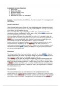
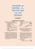
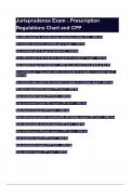
The figure below represents a pV [ p in Pa × 104and V in m3] diagram for 7.50 moles of an ideal diatomic
gas taken through the cycle a → b → c.
(a) Calculate the highest temperature reached by the gas during the cycle (4)
(b) What net work does the gas do during the cycle? (4)
(c) How much heat is exchanged with the gas during part bc of the cycle? Does it enter or
leave the gas? (4)
(d) What is the change in the internal (thermal) energy of the gas during part bc of the cycle? (4)
(e) What is the change in the internal (thermal) energy of the gas during the entire cycle? (4)
[20]
Question 2
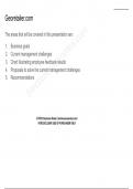
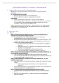
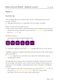
(a) The figure below shows three electric charges labeled Q1,Q2,Q3, and some electric field lines in the
region surrounding the charges. What are the signs of the three charges? (6)
[TURN OVER]
Page 2 of 5 PHY1506
(b) A 400-g piece of metal at 120.0◦C is dropped into a cup containing 450 g of water at 15 .0◦C.The
final temperature of the system is measured to be 40 .0◦C.Calculate the specific heat of the metal,
assuming no heat is exchanged with the surroundings or the cup. The specific heat of water is
4186 J/(kg.K). (6)
(c) Why doing a change of phase, heat is absorbed but the temperature does not rise? (3)
[15]
Question 3
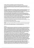
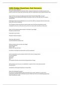
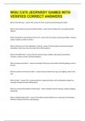
(a) Two positive point charges +4 .00 µC and +2.00µC are placed at the opposite corners of a rectangle
as shown in the figure. What are the potentials at points A and B (relative to infinity) due to these
charges? (10)
(b) A heat engine with an efficiency of 30.0% performs 2500 J of work. How much heat is discharged to
the lower temperature reservoir? (10)
[20]
Question 4
(a) The magnetic field of a moving charge is given by
~B =µ
0
4π
qv sin θ
r2.
(i) Which law does this equation represent? (2)
(ii)What do r,µ,v and θ represent? (4)
(b) What is an electromagnetic induction? (3)
(c) State Faraday’s law (6)
[15]
[TURN OVER]
Page 3 of 5 PHY1506
Question 5
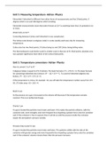
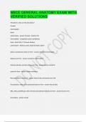
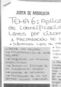
Consider the electric circuit as shown in the figure below, find:
(a) the equivalent resistor of the circuit, (5)
(b) the current flowing through each resistor, (8)
(c) the potential difference across each resistor. (7)
( Please summarize your results in a table for an easy reading)
[20]
Question 6
An RLC circuit consists of a 10 Ω resistor, a 1.0 mH and a 1 .0 µF capacitor,in series and connected to
a (10V ) cos ωt.Calculate:
(a) the resonance frequency (3),
(b) the resistor and capacitor voltages ( VRand VC). (7)
[10]
TOTAL: 100 Marks
[TURN OVER]
Page 4 of 5
Question 1
The figure below represents a pV [ p in Pa × 104and V in m3] diagram for 7.50 moles of an ideal diatomic
gas taken through the cycle a → b → c.
(a) Calculate the highest temperature reached by the gas during the cycle (4)
(b) What net work does the gas do during the cycle? (4)
(c) How much heat is exchanged with the gas during part bc of the cycle? Does it enter or
leave the gas? (4)
(d) What is the change in the internal (thermal) energy of the gas during part bc of the cycle? (4)
(e) What is the change in the internal (thermal) energy of the gas during the entire cycle? (4)
[20]
Question 2
(a) The figure below shows three electric charges labeled Q1,Q2,Q3, and some electric field lines in the
region surrounding the charges. What are the signs of the three charges? (6)
[TURN OVER]
Page 2 of 5 PHY1506
(b) A 400-g piece of metal at 120.0◦C is dropped into a cup containing 450 g of water at 15 .0◦C.The
final temperature of the system is measured to be 40 .0◦C.Calculate the specific heat of the metal,
assuming no heat is exchanged with the surroundings or the cup. The specific heat of water is
4186 J/(kg.K). (6)
(c) Why doing a change of phase, heat is absorbed but the temperature does not rise? (3)
[15]
Question 3
(a) Two positive point charges +4 .00 µC and +2.00µC are placed at the opposite corners of a rectangle
as shown in the figure. What are the potentials at points A and B (relative to infinity) due to these
charges? (10)
(b) A heat engine with an efficiency of 30.0% performs 2500 J of work. How much heat is discharged to
the lower temperature reservoir? (10)
[20]
Question 4
(a) The magnetic field of a moving charge is given by
~B =µ
0
4π
qv sin θ
r2.
(i) Which law does this equation represent? (2)
(ii)What do r,µ,v and θ represent? (4)
(b) What is an electromagnetic induction? (3)
(c) State Faraday’s law (6)
[15]
[TURN OVER]
Page 3 of 5 PHY1506
Question 5
Consider the electric circuit as shown in the figure below, find:
(a) the equivalent resistor of the circuit, (5)
(b) the current flowing through each resistor, (8)
(c) the potential difference across each resistor. (7)
( Please summarize your results in a table for an easy reading)
[20]
Question 6
An RLC circuit consists of a 10 Ω resistor, a 1.0 mH and a 1 .0 µF capacitor,in series and connected to
a (10V ) cos ωt.Calculate:
(a) the resonance frequency (3),
(b) the resistor and capacitor voltages ( VRand VC). (7)
[10]
TOTAL: 100 Marks
[TURN OVER]
Page 4 of 5