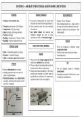
ATPL - 021 - AGK fait référence à une section du programme de la licence de pilote de ligne (ATPL) axée sur l'étude des systèmes et connaissances générales des aéronefs (AGK, Aircraft General Knowledge). Voici les points clés qui pourraient être résumés dans ce domaine :
Structures...
SYSTEMS
1
–
AIRCRAFT
STRUCTURES
&
AERODYNAMIC
LIMITATIONS
STRESSES
TENSILE
STRENGTH
BEAM
MOMENTS
• Load
per
cross
sectional
area.
• Even
more
stretching
after
the
elastic
limit
• Moment
=
Force
x
Distance
will
cause
the
material
to
neck
(get
thinner).
• Max
bending
moment
on
a
wing
occurs
at
• Tension
(tensile
stress)
–
EG/
fuselage
• Stress
increases
since
the
cross
sectional
the
root
due
to
furthest
distance
from
load.
• Compression
–
EG/
top
of
wing
area
reduces.
• Support
is
thicker
and
end
is
thinner
–
thus
• Shear
(cutting)
–
EG/
wing
root
bolts
• Just
before
failure,
the
material
has
saving
weight.
• Torsion
(twisting)
maximum
strength
per
unit
of
cross
• Bending
–
Compression
+
Tension
+
Shear
sectional
area.
This
is
the
tensile
strength.
• Buckling
–
Uneven
compressive
load
STRUTS
TYPES
OF
LOADS
BASIC
STRUCTURAL
MEMBERS
• Struts
are
designed
to
withstand
mainly
compressive
loads.
• Static
–
Continually
applied,
no
change.
• Tend
to
buckle
under
load
before
failure.
• Dynamic
–
Constantly
changes
BEAMS
• Normally
hollow.
• Cyclic
–
Continually
applied
and
removed.
• They
can
be
either
simply
supported
(both
ends)
or
be
cantilever
(one
end
only).
TIE
STRAINS
• They
are
subject
to
bending
with
one
side
in
tension
and
the
other
in
compression.
• Ties
are
designed
mainly
to
withstand
• Strain
is
deformation
due
to
stress.
• Beams
in
aircraft
are
usually
an
I
/
H
section
tensile
loads.
• Initially
proportional
to
stress
and
will
and
the
same
strength
as
a
whole
beam
is
• Normally
constructed
of
solid
rod
or
a
wire
return
to
original
shape.
possible
due
to
interaction
of
compression
of
relatively
small
diameter.
• Plastic
deformation
-‐
Once
elastic
limit
is
and
tension
(but
it
is
of
course
lighter).
exceeded,
stretching
will
continue
but
will
not
return
to
original.
, SYSTEMS
1
–
AIRCRAFT
STRUCTURES
&
AERODYNAMIC
LIMITATIONS
THE
FUSELAGE
SEMI
-‐
MONOCOQUE
FUSELAGE
FUSELAGE
TYPES
• Majority
of
stress
dissipated
by
internal
• Circular
THE
FUSELAGE
components
and
very
little
by
the
skin.
o Good
for
containing
hoop
stress
• Gives
a
strong,
relatively
light
structure
with
o Lowest
amount
of
skin
drag
for
volume
• Accommodates
crew
and
payload
lots
of
space.
o Bad
for
space
• Supports
other
components
of
the
aircraft.
• Longerons
–
Longitudinal
(Main
stresses)
• Rectangular
• Subject
to
a
number
of
stresses
in
flight:
• Frames
–
Vertical
(Stress
+
gives
rigidity)
o Max
use
of
space
o Nose
and
tail
droop
down
causing
• Stringers
–
Support
the
skin
o Bad
for
pressurization
tension
on
top
and
compression
• Bulkheads
–
Airtight
for
pressurisation
o Used
in
light
a/c
and
non
pressurised
underneath.
transporters.
o Compounded
by
tail
exerting
downforce
• Oval
o A380
Design
o Good
use
of
space
TRUSS
TYPE
FUSELAGE
o Best
compromise
for
pressurisation
o Requires
very
strong
floor
beams.
• Frame
supports
the
load,
skin
is
merely
to
o Double
bubble
section
can
be
used
to
cover
and
reduce
drag.
reduce
total
tension
on
each
frame.
• Longerons
run
longitudinally
and
provide
the
main
load
bearing.
• Supported
both
vertically,
horizontally
and
PRIMARY
VS
SECONDARY
STRUCTURE
diagonally
with
web
members
to
give
complete
rigidity.
• Primary
-‐
A
critical
load-‐bearing
structure.
• No
space
for
payload
so
mainly
on
light
• Secondary
–
Structural
elements
mainly
to
aircraft.
HOOP
STRESS
provide
enhanced
aerodynamics.
• Large
forces
which
push
the
fuselage
MONOCOQUE
FUSELAGE
outwards
as
a
result
of
pressurisation.
• Tension
in
frames.
• Skin
takes
all
the
load.
• Bending
in
longerons,
stringers
and
skin.
• No
internal
load
bearing
structure
although
former
rings
sometimes
fitted
to
give
shape.
• No
ability
to
add
doors
etc
otherwise
ability
of
skin
to
withstand
stress
is
destroyed.
, SYSTEMS
1
–
AIRCRAFT
STRUCTURES
&
AERODYNAMIC
LIMITATIONS
THE
WINGS
/
MAINPLANE
TORSION
BOX
THE
TAIL
• Supporting
the
twisting
motion
of
lift
of
the
THE
WINGS
wings.
TAIL
SECTION
• Links
the
spars,
skins
and
ribs.
• Semi-‐monocoque
design
• One
in
each
wing
plus
a
centre
spar
to
link
• Semi-‐monocoque
design
• Spars
–
Withstand
bending
and
torsional
the
two
wings.
loads
• Wing
torsion
can
result
from
positive
sweep
• Ribs
–
Gives
shape.
Holes
make
it
stronger
and
lighter.
• Stringers
–
Support
the
skin.
• Centre
spar
can
also
be
included
to
supported
undercarriage
etc.
SANDWICH
TYPE
CONSTRUCTION
HONEYCOMB
CONSTRUCTION
, SYSTEMS
1
–
AIRCRAFT
STRUCTURES
&
AERODYNAMIC
LIMITATIONS
WING
BENDING
ON
GROUND
AIRCRAFT
STRUCTURAL
MATERIALS
ATTACHMENT
METHODS
• Wings
and
undercarriage
on
ground
are
• Aluminum
Alloy
• Riveting
subject
to
heavy
loads
so
the
Maximum
o Raw
aluminum
lacks
strength
+
rigidity
o Can
be
flush
or
round
headed
Ramp
Mass
is
set
to
limit
stress.
o Mixed
with
4-‐6%
copper
=
Duralumin
o Flush
type
is
more
aerodynamic
but
o Good
conductor
and
improved
strength
more
expensive.
o Difficult
to
weld
&
good
thermal
o Cracks
can
originate
at
rivet
points.
WING
BENDING
IN
FLIGHT
conductivity
• Bolts
• Magnesium
Alloy
o Allows
for
separation
of
materials
when
• Lift
acts
to
bend
wings
upwards.
o Lightweight
but
lack
strength
and
are
required.
• Fuel
and
engines
help
to
reduce
bending.
brittle.
o Vibrations
can
cause
nuts
to
become
• The
greatest
bending
moment
at
the
wing
o Easily
moulded
into
complex
shapes
loose.
This
is
prevented
by
wire
locking.
root
occurs
with
high
fuselage
mass
and
o Used
in
gearbox
casing
and
wheel
rims
• Welding
zero
fuel
(wings
bending
up).
The
• Steel
o A
very
tough
bond
is
created.
maximum
zero
fuel
mass
is
therefore
set
o Bolts
etc
o Load
spread
over
a
large
area.
to
limit
stress.
o Carbon
added
to
improve
load
bearing
• Pinning
• The
leading
edge
is
subject
to
compression
o +
chromium
=
stainless
steel
o Good
for
attaching
components
that
then
tension
(from
root
to
tip)
• Titanium
experience
shear
stress.
o Very
resistance
to
high
temperatures
o Can
be
undone
at
a
later
date.
o Turbines
etc
• Adhesives
• Plastic
o Easy
to
use
and
can
bond
large
areas.
FUSELAGE
BENDING
IN
FLIGHT
o Easy
to
mould
but
has
poor
strength.
o Permanent
and
have
relatively
low
o Interiors
mechanical
strength.
• Bending
moment
around
fuselage
due
to
• Fibre
Reinforced
Plastics
(FRPs)
download
on
the
horizontal
stabiliser
to
o Layers
of
fibres
(glass,
Kevlar,
carbon)
counteract
the
lift-‐weight
couple.
provide
the
strength
and
the
filler
gives
the
stiffness.
o CFRP
=
Carbon
Fibre
o KFRP
=
Kevlar
o GFRP
=
Glass
Les avantages d'acheter des résumés chez Stuvia:
Qualité garantie par les avis des clients
Les clients de Stuvia ont évalués plus de 700 000 résumés. C'est comme ça que vous savez que vous achetez les meilleurs documents.
L’achat facile et rapide
Vous pouvez payer rapidement avec iDeal, carte de crédit ou Stuvia-crédit pour les résumés. Il n'y a pas d'adhésion nécessaire.
Focus sur l’essentiel
Vos camarades écrivent eux-mêmes les notes d’étude, c’est pourquoi les documents sont toujours fiables et à jour. Cela garantit que vous arrivez rapidement au coeur du matériel.
Foire aux questions
Qu'est-ce que j'obtiens en achetant ce document ?
Vous obtenez un PDF, disponible immédiatement après votre achat. Le document acheté est accessible à tout moment, n'importe où et indéfiniment via votre profil.
Garantie de remboursement : comment ça marche ?
Notre garantie de satisfaction garantit que vous trouverez toujours un document d'étude qui vous convient. Vous remplissez un formulaire et notre équipe du service client s'occupe du reste.
Auprès de qui est-ce que j'achète ce résumé ?
Stuvia est une place de marché. Alors, vous n'achetez donc pas ce document chez nous, mais auprès du vendeur decarpentryaimeric. Stuvia facilite les paiements au vendeur.
Est-ce que j'aurai un abonnement?
Non, vous n'achetez ce résumé que pour 9,16 €. Vous n'êtes lié à rien après votre achat.