100% satisfaction guarantee Immediately available after payment Both online and in PDF No strings attached
logo-home
Automatic Control Systems £6.12   Add to cart

Exam (elaborations)

Automatic Control Systems

 1 view  0 purchase
  • Module
  • Institution

These set of notes covers the basics as well as advanced course space of automatic control system. It has notes covering topics such as TIME-DOMAIN ANALYSIS OF CONTROL SYSTEMS CONTROL SYSTEM COMPONENTS AND DEVICES STABILITY OF LINEAR CONTROL SYSTEMS. Transfer Function, Block Diagram and Signal...

[Show more]
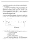
Preview 2 out of 11  pages

  • May 27, 2021
  • 11
  • 2019/2020
  • Exam (elaborations)
  • Answers
avatar-seller
BASIC CONTROL ACTIONS & CONTROLLER CHARACTERISTICS
7.1 INTRODUCTION :
The automatic controller determines the value of controlled variable, compare the actual value to
the desired value (reference input), determines the deviation and produces a control signal that will
reduce the deviation to zero or to a smallest possible value. The method by which the automatic
controller produces the control signal is called mode of control or control action. Figure 7.1 is a block
diagram of an industrial control system, which consists of an automatic controller, an actuator, a plant
and a sensor (measuring element). The controller detects the actuating error signal, which is usually at a
very low power level, and amplifies it to a sufficiently high level. The output of an automatic controller
is fed to an actuator, such as an electric motor, a hydraulic motor or a pneumatic motor or valve. (The
actuator is a power device that produces the input to the plant according to the control signal so that the
output signal will approach the reference input signal).
The sensor or measuring element is a device that converts the output variable into another
suitable variable, such as a displacement, pressure or voltage that can be used to compare the output to
the reference input signal. This element is in the feedback path of the closed-loop system. The set point
of the controller must be converted to a reference input with the same units as the feedback signal from
the sensor or measuring element.

Automatic controller

Error detector
Reference
input Output
Amplifier Actuator Plant
(Set point) +
-
Actuating
error signal


Sensor
(Measuring element)

Figure 7.1 Block diagram of an industrial control system.
7.2 CLASSIFICATIONS OF INDUSTRIAL CONTROLLERS:
Controllers are classified depending upon the type of controlling action used. Therefore, they can
be classified as,
(i) Two-position or ON-OFF controllers.
(ii) Proportional (P) controllers.
(iii) Integral (I) controllers.
(iv) Derivative (D) controllers.
(v) Proportional-plus-integral (PI) controllers.
(vi) Proportional-plus-derivative (PD) controllers.
(vii) Proportional-plus-integral-plus-derivative (PID) controllers.
They can also be classified according to the power source used for actuating mechanisms, such
as electrical, electronics pneumatic and hydraulic controllers. Hydraulic controllers are used for
controlling heavy loads; pneumatic controllers are suitable for shop floor applications.

, The selection of a particular type of controller depends on the nature of plant, operating
conditions such as safety, cost, availability, accuracy, weight and size.

7.2 TWO POSITION OR ON-OFF CONTROLLER;
These types of controllers are simple and inexpensive and are generally employed on home heating
systems, domestic water heaters and industrial control systems.

In this type of control the output of the controller is quickly changed to either a maximum or minimum
value depending upon whether the controlled variable ( b ) is greater or less than the set point or in other
words depends upon the actuating error signal (e). The minimum value is usually zero.
Let, m = output of the controller.
M 1 = Maximum value of output of the controller.
M 2 = Minimum value of output of the controller.
e = actuating error signal or deviation.
The equations for two position control will be
m = M1 When e > 0.
m = M2 When e < 0.
The minimum value M 2 is usually either zero or - M 1
Differential gap

e m e m
Set
Set + point
point +
- b - b


(a) (b)
Figure 7.2.
The block diagram of two position controllers is shown in fig.7.2. In On-OFF controller there is
an overlap as the error increases through zero. This overlap creates a span of error. During this span of
error, there is no change in the controller output. This span of error is known as dead zone or dead zone
or dead band. Dead band is shown in fig. 7.3.

From fig. 7.3, it is clear that till the error changes by Δe there is no change in the controller
output. Similarly, while decreasing the error must decrease beyond Δe below 0 to change the controller
output. Hence during 2Δe there is no change in the controller output. This zone is known as differential
gap. The differential gap can also be defined as the range through which the actuating error signal must
move before the switching occurs.

In this type of controller, the control variable always oscillates with a frequency which increases
with decreasing width of the dead zone (differential gap). The decrease in dead zone, the number of ON-
OFF switching of controller increases, hence therefore the useful life of the component decreases. Hence
dead band should be designed to prevent the oscillations in ON-OFF controllers.

The benefits of buying summaries with Stuvia:

Guaranteed quality through customer reviews

Guaranteed quality through customer reviews

Stuvia customers have reviewed more than 700,000 summaries. This how you know that you are buying the best documents.

Quick and easy check-out

Quick and easy check-out

You can quickly pay through credit card for the summaries. There is no membership needed.

Focus on what matters

Focus on what matters

Your fellow students write the study notes themselves, which is why the documents are always reliable and up-to-date. This ensures you quickly get to the core!

Frequently asked questions

What do I get when I buy this document?

You get a PDF, available immediately after your purchase. The purchased document is accessible anytime, anywhere and indefinitely through your profile.

Satisfaction guarantee: how does it work?

Our satisfaction guarantee ensures that you always find a study document that suits you well. You fill out a form, and our customer service team takes care of the rest.

Who am I buying these notes from?

Stuvia is a marketplace, so you are not buying this document from us, but from seller piyub8417. Stuvia facilitates payment to the seller.

Will I be stuck with a subscription?

No, you only buy these notes for £6.12. You're not tied to anything after your purchase.

Can Stuvia be trusted?

4.6 stars on Google & Trustpilot (+1000 reviews)

76747 documents were sold in the last 30 days

Founded in 2010, the go-to place to buy revision notes and other study material for 14 years now

Start selling
£6.12
  • (0)
  Add to cart