Pumpjack Optimisation
I. Introduction
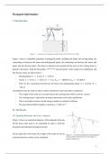
Figure 1 – schematic of a pumpjack model (University of Warwick, 2024)
Figure 1 shows a simplified schematic of pumpjack model, including the frame, the rocking beam, the
connecting rod between the beam and underground pump, the connecting rod between the motor and
beam, and the driving motor. The frame is pinned to the ground and the pivot of the rocking beam is
pinned to the frame. With the ID number, ********, the parameters of the model were established, and
all relevant values are shown below:
- Rocking Beam: 𝐴 = 2.2 𝑚, 𝐵 = 2.96 𝑚
- Frame: 𝐼 = 9.5 𝑚, 𝐽 = 8.5 𝑚, 𝐻 = 5 𝑚, 𝐹!" = −10400 𝑁, 𝐹!# = −37200 𝑁
- Hole for the connecting rod between the beam and underground pump: 𝑑 = 0.16 𝑚, 𝐷 =
146 𝑚
Assumptions must be made in order to make calculations easier and reduce complexity:
- The weight of the crude oil is a point load on the rocking beam which is always vertical
- The rocking beam is rigid when in motion and assume to be static equilibrium
- This is an isolated system, and all energy transfers are perfectly efficient
- The gravitational field strength is constant, 𝑔 = 9.81 𝑚𝑠 $%
II. The Beam
II.I. Bending Moments and Force Analysis
Figure 2 shows an annotated diagram of the pumpjack showing
all the forces that need to be calculated in order to find the
maximum and minimum bending moments.
On the right side of the beam, the weight of the crude oil acts as Figure 2 – an annotated diagram of the pumpjack,
a downwards force which can be calculated: showing all the relevant forces and angles, at
negative angles of 𝛾.
1
, &
𝑃 ='×𝑔 ∴ 𝑃 = −24478 𝑁
Bending moment analysis about point C to find the forces perpendicular to the beam:
∑𝑀! = 0 ∴ 𝐹(# 𝑅(! + 𝑃# 𝑅!) = 0
!
* + ,-./ $012#$
"
If 𝑃# = 𝑃 sin E % − 𝛾G then 𝐹(# = −
2%#
The different 𝛾 angles were given, therefore using MATLAB these values
were used to calculate the moments about point C. As shown in figure 3,
the moments on either side of point C are equal and opposite which proves
that this system is in equilibrium. Moreover, the maximum and minimum
bending moments can be deduced:
𝑀34" = 72455 𝑁 𝑀356 = 66079 𝑁
The maximum bending moment occurs at 𝛾 = 0, and the minimum bending
moment occurs at 𝛾 = −0.42264 𝑟𝑎𝑑. This is because when the beam is Figure 3 – the gamma angles,
bending moments at point B, and
horizontal, the weight of the crude oil has the most effect since it is the bending moments at point D
respectively.
perpendicular. However, when the beam is at its maximum or minimum
angle, the bending moment decreases because the force is no longer perpendicular to the beam. Taking
*
reference from the sine graph, at % , the graph is at its peak and on either side of the peak the graph
decreases. Which explains why the bending moments decrease as the beam moves away from the
horizontal position.
Force analysis for the forces parallel and perpendicular to the rocking beam:
∑𝐹# = 0 ∑𝐹" = 0
𝐹(# + 𝐹!# + 𝑃# = 0 𝐹(" + 𝐹!" + 𝑃" = 0
!
* +& ,-./ $012#$ * *
"
𝐹!# = − 𝑃# sin E % − 𝛾G + 2%#
𝐹!" = −𝐹(# 𝑐𝑜𝑠 E % − 𝛾G − 𝑃# 𝑐𝑜𝑠 E % − 𝛾G
All the vertical forces are constant whereas the horizontal forces
change in regard to the angle of the beam. Therefore, we can
calculate all the horizontal forces at the different 𝛾 angles, as
shown in figure 4. 𝐹(" and 𝑃" have the opposite sign and change
sign depending on the sign of 𝛾. Whereas 𝐹!# is the negative
difference between 𝐹(" and 𝑃" .
Maximum horizontal forces of the rocking beam:
Figure 4 – the angle and the horizontal forces at
𝐹(" = −13509 𝑁 𝐹!" = 3468.4𝑁 𝑃" = 10040 𝑁 points B, C, and D respectively.
2


